
Product Category
Security, Fire & Safety > security system
Trademark
BISEN
Business Type: Manufacturer
Main Products:Traffic BarrierAutomatic Door Operators
ID:20111338954
Category: Security, Fire & Safety security system
MOQ:1.00 Piece(s)
System Detect VehicleCar Radar Sensor
L/CT/T
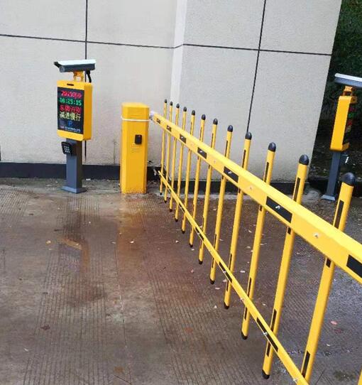
BS-RD-A06 barrier gate control radar can be used to the access of parking lots or underground garages. It’s capable of precisely controlling of the barrier gate in various environment such as different illumination and climates. It has the advantages of small size, high detection accuracy and very high integration.
The radar works in the frequency band of 77-81Giga-Hertzs with Linear Frequency Modulation (LFM) and the available bandwidth can be set as much as 4 Giga-Hertz. The range resolution can be less than 4 centimeters and the rang measuring accuracy could be better than 2 centimeters. The radar uses two transmitting antennas and four receivingantennas, working inMultiple Input Multiple Output (MIMO) mode, which enables extremely high azimuth resolution and azimuth measurement accuracy . BS-RD-A06 radar can correctly identify and distinguish pedestrians and vehicles, which makes the barrier gate more intelligent and can trigger the gate bar falling down when there is no objects under the gate. And the radar will trigger the gate bar lifting as soon as possible when there exist sudden entry objects within the access zone, which enables the smash proof of vehicles orpedestrians.
Terms | Parameter | Value |
Working Condition | Input Voltage(Volts) | 10~16 |
Temperature Range(℃) | -40℃~85℃ | |
Power(W) | < 2.5 | |
Water Rissistance Level | IP67 | |
Connection Interface | TTL | |
Size(mm) | 102*72*32 | |
Detection zone | Along Road Width | Default±0.5m (configurable within ±1m) |
Cross Road Range | Default 3 m (configurable within 6 m) | |
Upgrade debugging | Online debugging | Serial Port Debug |
Online update | Serial Port Upgrade |
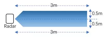
LED indicators: There are two LED indicators on the surface of the front surface of BS-RD-A06 radar. The red LED is the power state lamp which will stay on when the power supply is turned on; The green LED is the operating status lamp which will be automatically trigger on when objects detected in the access area and it goes off when there is no objects. Detection Zone configuration: The default detection Zone of the radar is 3 meters forward times. 0.5 meters on the left and right sides. A configurable detection area can be set by corresponding PC software. Configuration parameters saving and reload: Configuration such as detection area could be automatically saved, and the latest configuration parameters after power failure and restart can be reloaded. | |
TTL interface:
The interface between radar and motherboard of barrier gate adopt TTL interface which provide long range and robust communication between two devices.
Firmware upgrade:
The firmware can be upgraded online through TTL interface with host computer without taking off the cover board and the new firmware can take effect just by restarting the power of radar.
Stable performance:
Millimeter wave radar sensingcapablity stay nearly the same under different light illumination, climate such as rain, fog or snow and dust.
There are 8 wires interface among which some of them should be connected to the mainboard of barrier gate. The definition of each interface is shown as followling table.
NO | CABLE ID | Color | Description |
1 | VCC | Red | positive pole |
2 | GND | Black | negative pole |
3 | GND | Yellow | Reserved Ground |
4 | A+ | White | RX |
5 | B- | Gray | TX |
6 | J1 | Brown | Gate control signal (gateclosed) |
7 | - | Blue | public common signal of barrer gate |
8 | J2 | Green | Gate control signal (gateopen) |
Here are the detailed connections of these interface to the gate control board.
Power supply connection:
The red wire("VCC")MUST be connected to the positive output terminal of the 12V power supply,
The black wire ("GND")MUST be connected to the negative output terminal of the power supply.
Barrier gate control signal:
The brown and blue wires are normally closed signals of the radar onboard relay.
The green and blue wires are normally open signals of the radar onboard relay.
The green and blue wires MUSTbe connected to the originally loop detector interface and the public common signal interface.
Communication connection: (optional for device debug)
The white wire ("RX") is connected to the TX end of USB to TTL,
The gray wire ("TX") is connected to the RX end of USB to TTL,
The yellow wire ("GND") is used as TTL serial port common ground wire.
The final connection is shown as follows:
Range scope setting of the BS-RD-A06 radar can be archieved through the following ways: Manual Self-Learning Setting and Host Software Setting. Clients can choose suitable and convinent setting way.
Manual Self-Learning Setting
Radar working mode and range scopecan be configured automatically by walking around in front of the radar FOV(Filed Of View) according to the type of gate.
Operation Steps:
For Straight-bar or Fence Gate
(1) Trigger the dial switch to state ”ON”.
(2) Connect the radar to the power supply, and the LED indicator on the surface of radar begins to blink after 3 seconds after power on, which indicates that the radar is working on the self-learning mode.
(3) Client is required to keep walking from radar to the end of the gate bar back and forth UNTIL the blinking green LED stops twinkling and keeps on. Then the range scope will be set to stable maximum range along the radar normal direction. (Currently the maximum configurablerange is 6 meters).
For AdvertisementGate
(1) Trigger the dial switch to state ”ON”.
(2) Connect the radar to the power supply.Trigger the dial switch back to the original position at least 1 second later after the power on.The LED indicator on the surface of radar begins to blink after 3 seconds after power on, which indicates that the radar is working on the self-learning mode.
(3)Client is required to keep walking from radar to the end of the gate bar back and forth UNTIL the blinking green LED stops twinkling and keeps ‘OFF’. Then the range scope will be set to stable maximum range along the radar normal direction. (Currently the maximum configurable range is 6 meters).
4.When the green light is off, the radar can work normally after power reset.
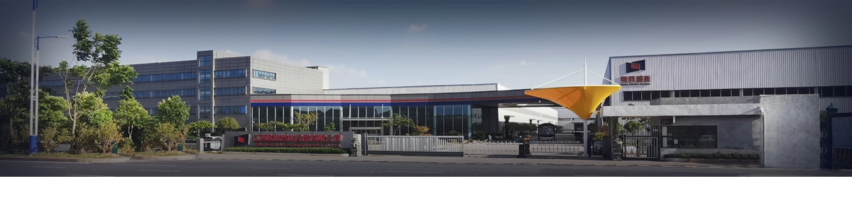
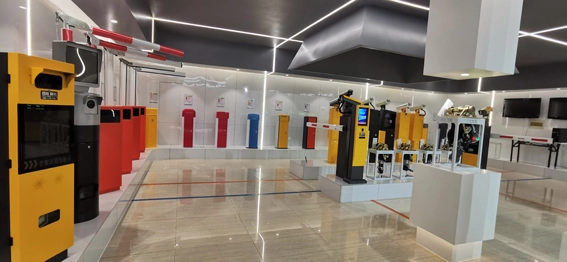
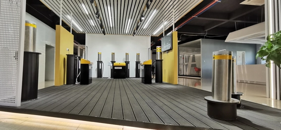
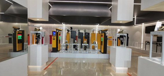
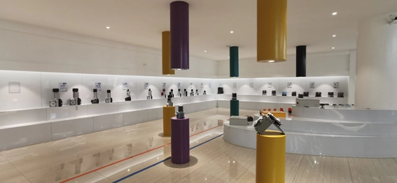
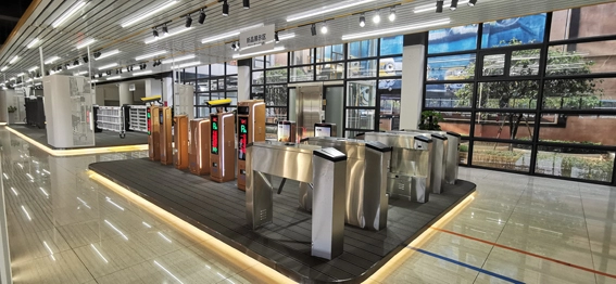
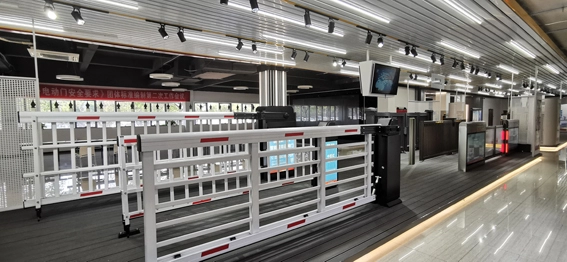
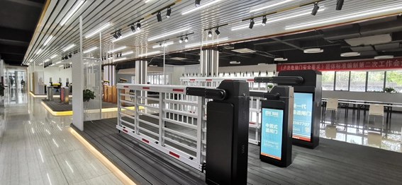
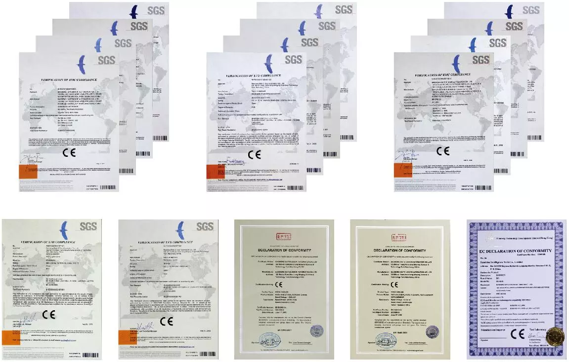
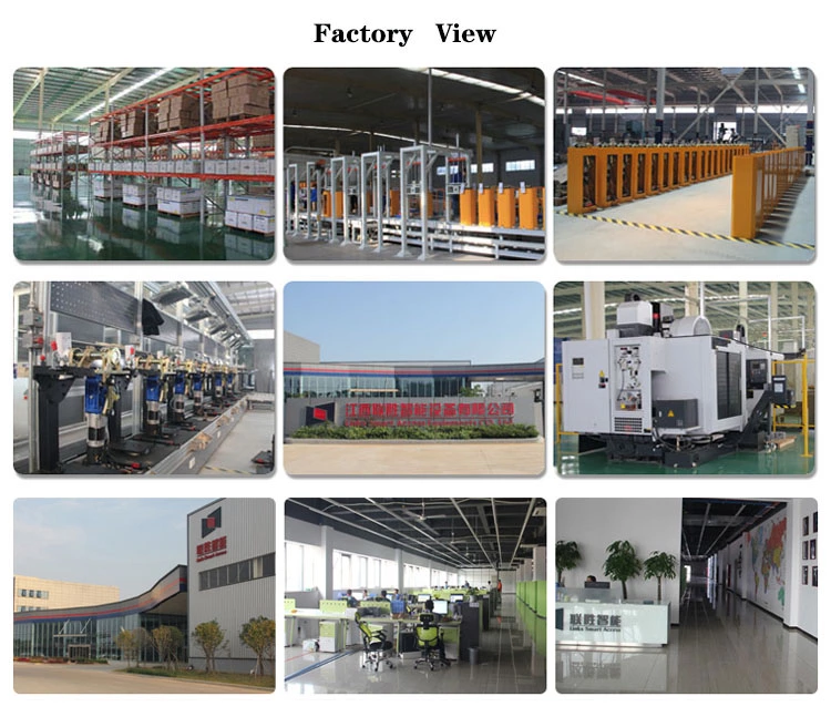
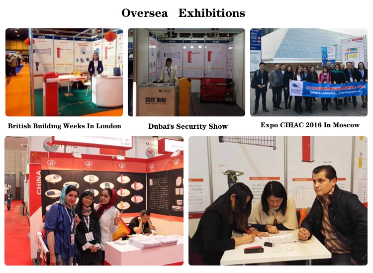
BISEN SMART ACCESS CO,.LTD was established in 1999, located in NanChang, China.
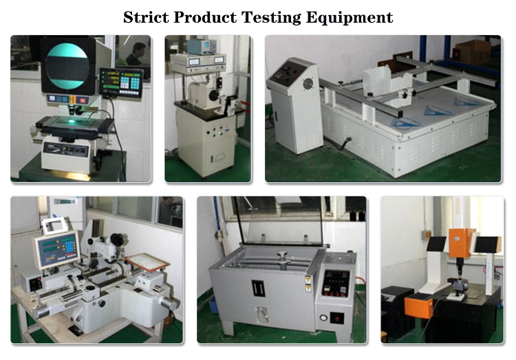
We are the biggest professional manufacturer for parking management system and equipments, gate and door automatic operators in China. more than 70 experienced engineers are engaging in R&D team , and more than 500 employees are working in manufacturer and service. We can provide quality ODM / OEM service for customers.
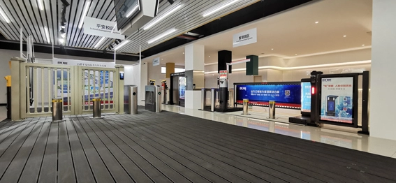
Our main products: Parking system auto-barrier gate, Sliding gate opener, Swing gate opener, Industrial sectional door opener, anti-terrorism road blocker, Hydraulic bollard, Pedestrian gate, Entrance control system etc.
Q: Are you trading company or manufacturer ?
A: We are factory.
Q: How long is your delivery time?
A: Generally it is 5-10 days, or it is 15-20 days if the quantity is very big. It is according to quantity.
Q: Do you provide samples ? Is it free or extra ?
A: We could offer the sample for charge, freight collect.
Q: What is your terms of payment ?
A: Payment<=1000USD, 100% in advance. Payment>=1000USD, 30% T/T in advance, balance before shippment.
If you have another question, pls feel free to contact us as.

Business Type:Manufacturer
Online Supplier